
Here’s a quick review of the basic flight instruments as might be found in a middle-aged airplane that hasn’t been upgraded to modern electronic displays.
These instruments allow the pilot to maintain control while flying without visual reference to the either ground or horizon and help the pilot avoid spatial disorientation. This is called flying in IMC (instrument meteorological conditions) while talking to ATC (air traffic control) and operating under IFR (instrument flight rules). Aviation has a multitude of acronyms.
“Wait!”, you say, “I’ve got outstanding balance. I’m sure I could keep the airplane level and in control, even in the thickest cloud.”
This would be fatal to try. A shallow, balanced turn has about the same forces on your sense of balance as straight and level. The wings slowly fall off of level. Which way are you turning? Why is the air noise getting louder? There are also disorienting factors that give bad info, e.g., somatogravic illusion – acceleration is felt as pitching up or climbing. This fooling of the brain allows what are called “full-motion” simulators to mimic actual flying to the occupants.
The FAA requires certain flight equipment for instrument flight (not including engine and electrical system displays). In older instrument panels these are separate (and mechanical, that is, no software required):
Magnetic compass – no power required.
Airspeed indicator – no power required, just outside air pressure (static pressure) and slipstream air pressure (dynamic) from moving through the air.
Altimeter and vertical speed indicator – no power required, just static pressure.
Attitude indicator (aka, artificial horizon) and heading indicator- these are gyro instruments that use a gyro’s rigidity in space to show the airplane’s attitude (5° nose up, 15° right bank, for instance) and heading, respectively. Most commonly powered by a vacuum system that draws air over the notched rim of the gyro to cause it to spin.
Turn Coordinator or Turn and Slip (older) – electrically powered gyro instruments that use a gyro’s property of precession to display the direction and the rate of a turn compared to “standard”, which is 3°/second (two minutes to do a 360° turn). These instruments also have an inclinometer (unpowered, a shallow u-shaped bubble level) that displays if a turn is coordinated, slipping, or skidding.
These (excluding the compass) were consistently organized in what was often called a “six-pack” of two rows of 3 instruments (see Figure 1, from The Instrument Flight Manual, 8th Edition):
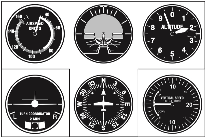
Top row, left to right: airspeed indicator (ASI, airspeed very low, near flaps-down stall), attitude indicator (A/I, wings level, nose well above horizon), altimeter (1,945 feet above sea level).
Second row: turn coordinator, (T/C or turn and slip, T/S- no turn, slip, or skid), heading indicator (H/I, North, 360°), then vertical speed indicator (VSI, zero, no climb or descent). The above displays match an airplane doing slow-flight, a training exercise where the pilot flies at a speed just above the aerodynamic stall.
This setup put the important A/I as the center of attention and the pilot would scan the instruments, passing through the A/I.
Another phrase commonly used was “Basic T” which referred to the group of four instruments excluding the T/C and VSI. This T-shape became an industry standard in the 1960’s. Instrument layouts before then could be rather, ah, interesting with that one way over there and this one over here, at least in THIS airplane. The Basic T and 6 Pack made transitioning from one model to another much easier.
Power Sources
For redundancy, the A/I and H/I in these airplanes have a different power source than the T/C to allow the pilot to both keep the wings level and make controlled turns when in IMC. A turning descent with airspeed rapidly building is one of the biggest threats to a pilot suffering from disorientation and has the descriptive name of “graveyard spiral”. Because of this redundancy, the loss of the electrical system or a failure of the turn coordinator itself would leave the vacuum-powered attitude and heading indicators available to the pilot. The loss of the vacuum system would leave the turn coordinator for the pilot to use to level the wings or to make controlled turns. This latter situation is a little tougher and is often simulated in training by covering the A/I and H/I. This is called flying “partial panel”.
Vacuum System
The two common methods of acquiring the low pressure to get air passing over the gyros of the attitude and heading indicators in these older airplanes are a Venturi tube either a vacuum pump.
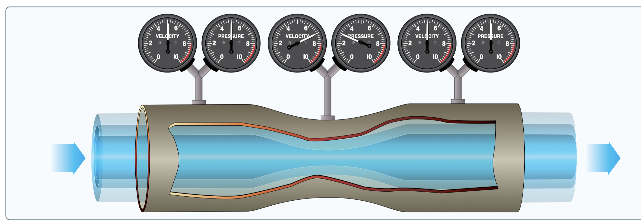
The Venturi tube uses Bernoulli’s Principle to lower the pressure in the tube, which is mounted on the outside of the airplane. The Principle holds that, as air is forced through a constriction (the Venturi), its speed increases, but its sideways pressure decreases. A small tube allows the low pressure of the Venturi tube to draw air from the cabin, past the gyros, and into the tube (actually, the higher pressure in the cabin seeks to equalize, so some is forced through the plumbing and into the Venturi). Figure 2 is from the FAA’s Pilot’s Handbook of Aeronautical Knowledge and illustrates the increase in velocity but decrease in pressure in the constriction.
On these older airplanes the Venturi tube is mounted on the outside of the fuselage and aligned with the airflow of the plane when in flight and the airflow from the propeller. The tube leading from the instruments would be attached where the middle gages are in Figure 2.
Figure 2
This system has the advantage of requiring no power, but the disadvantages of being subject to ice buildup on the tube when flying through cold, moist air and also needing a fair amount of airflow before the all-important instruments are “up to speed”.
As aviation progressed, vacuum pumps were built that attach to the engine and are geared to it, just like the oil pump and magnetos. The big advantage here is the vacuum system is powered as long as the engine is running. One item on the before takeoff checklist would be to verify the suction gage in the cockpit indicates in the green band (acceptable pressure) when the engine is running at medium power.
Modern planes or older ones upgraded to modern avionics (“aviation electronics) have the same instrumentation requirements, but the information is displayed on electronic screens in combination displays and are sweet indeed. These units often have internal batteries that will run for hours should the airplane’s main electrical system fail.
Since vacuum pumps are more susceptible to failure than the electronic “glass cockpits”, bystanders often note a smile on a pilot’s face as he or she peers into the engine compartment while preflighting the upgraded plane. The pilot is admiring the plate installed over the former home to the vacuum pump.
Figure 3 (The Student Pilot’s Flight Manual, 12th Edition).
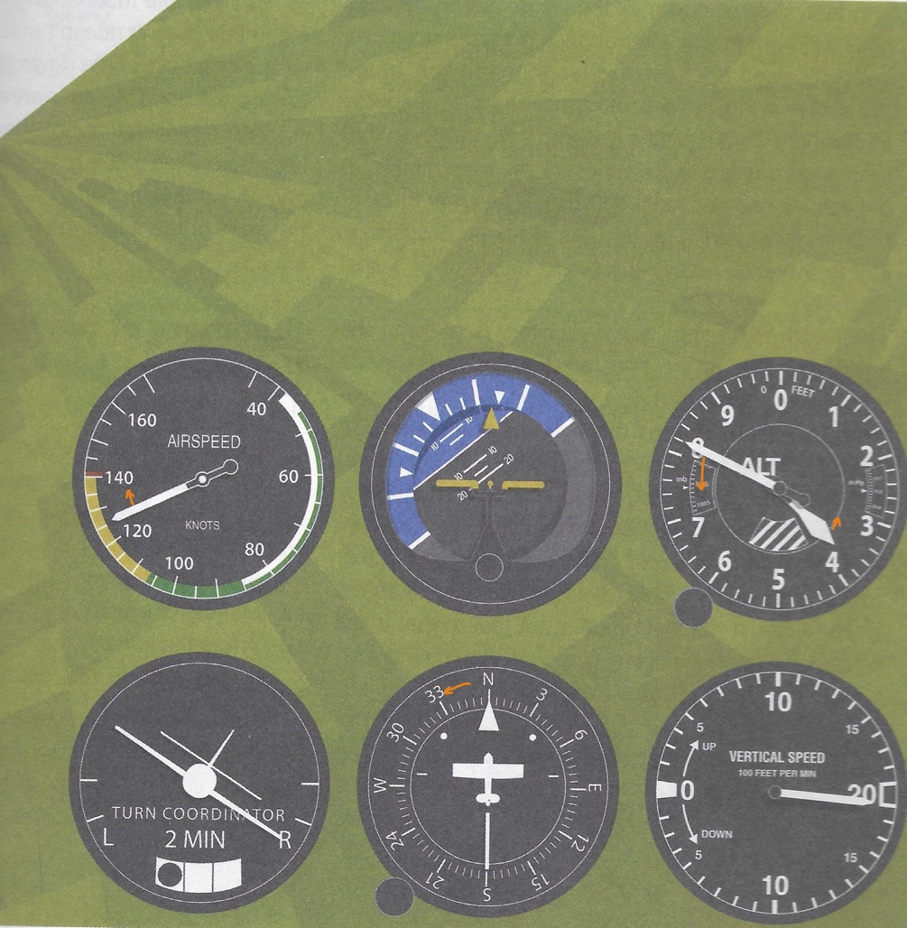
Graveyard Spiral-
The pilot has become disoriented in the clouds and failed to trust the instruments. At first the right wing gently dropped, which allowed the nose to lower, and the airplane has entered a power-on (cruise power is still set), ever tightening spiral dive. The airspeed is rapidly increasing and approaching the red line (never exceed speed), while the attitude indicator shows 25° nose below the horizon and close to 40° of right bank. The altimeter is winding down with the long hand moving very fast and the turn coordinator is at the stop in a right, skidding turn (the ball of the inclinometer is to the outside of the turn), well past the standard turn rate tic-mark. The card of the heading indicator is spinning to the left behind the airplane symbol and the vertical speed indicator is at its limit of 2000 feet per minute descent rate (the actual rate could be much more, but can’t be displayed).
Giving in to the natural tendency to pull on the yoke or stick will only tighten the spiral. The pilot has only a few seconds to make a recovery: close the throttle, roll the wings level (first), and carefully, gently pull out of the dive. Too often this type control loss ends in the airplane’s wings or tail failing due to high G-forces available at such high speed.
Trust (but crosscheck) your instruments.


